
- News
- Basics
- Products
- JP Job shop
- Exhibition
- Interview
- Statistic
- PR
- Download
- Special contents


![]()
 Japanese Cutting-Edge
Solutions for Metalworking


![]() Japanese Cutting-Edge
Japanese Cutting-Edge
Solutions for Metalworking
Basics
August 23, 2022


2-1. BT
2-2. BBT
2-3. HSK
2-4. Polygonal taper interface with flange contact surface
3-1. Collet chuck
3-2. Shrink chuck
3-3. Hydraulic chuck
3-4. Other tool holders
Key Points of tool holders
・ Tool holders act as an interface between a cutting tool and a machine tool.
・ BT shank is the most common type of standard in Japan.
・ There are three major types of holders for MCs: collet chuck, shrink chuck, and hydraulic chuck.
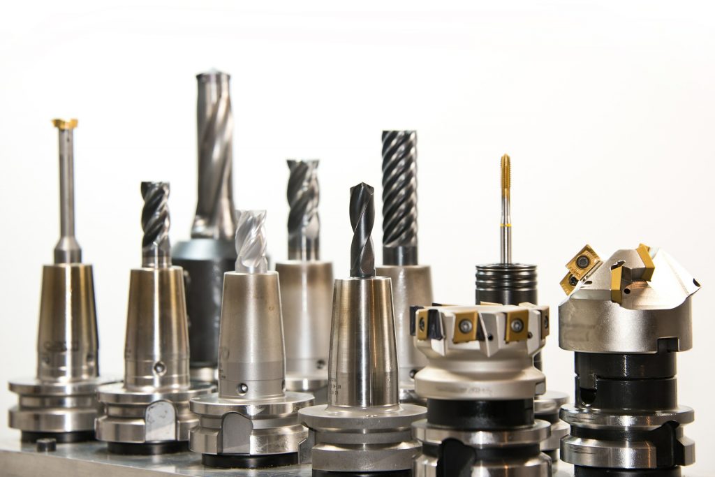
 Tool holders are devices that act as adapters to attach cutting tools to machine tools. They function as an interface between the cutting tool and the machine tool.
The performance of the tool holder directly affects the machining accuracy. In order to fully demonstrate the performance of the machine tool and cutting tool, the tool holder must have run-out accuracy, rigidity (resistance to deformation), and a high gripping force. Tool holders must meet these requirements without being defeated by centrifugal force or other forces, even when the spindle rotates at high speed. Run-out accuracy is a measure of how far a tool’s rotation deviates from the tool’s central axis. Higher run-out accuracy means a smaller shaking of the tool and higher accuracy of machining.
Tool holders are defined by standards in terms of shape and size. There are BT, BBT, HSK, etc. for machining centers (MC), and CAPTO for lathes, turning centers (TC), and lathe-based multitasking machines.
 BT stands for “bottle grip taper” and is marked by a tapered shank. It is used by attaching it to the spindle of an MC. The BT shank was originally developed in Japan and is widely used in manufacturing sites around the world.
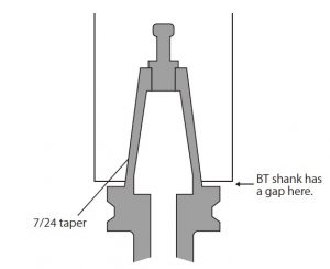
The size of the taper is fixed and is a 7/24 taper, where the diameter is 7 mm smaller for 24 mm axial direction. Depending on the diameter length of the largest part of the taper, there are nominal numbers such as BT30, BT40, and BT50.
NT shanks with 24/7 taper are also utilized in milling machines and boring machines that do not have an automatic tool changer (ATC). NT stands for “National Taper”.
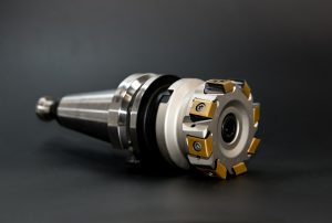
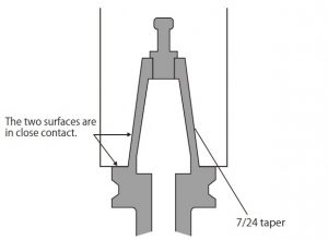 BBT shank is a standard developed independently by BIG DAISHOWA SEIKI, a Japanese leading tool holder manufacturer. It is difficult to distinguish the BBT shank from the BT shank at first sight, but the biggest difference is that BBT shanks are dual contact spindle system. “Dual contact” means that shank contact the spindle taper and spindle face simultaneously.
With the BT shank, only the tapered part is in close contact with the main spindle, and there is a gap between the shank end face and the end face of the main spindle. In this case, when the spindle rotates at high speed, the main spindle bore expands due to centrifugal force, causing the shank to be pulled into the spindle bore, which changes the position of the tool and may negatively affect machining accuracy, especially in the Z axis.
On the other hand, with a BBT shank, the shank end face and main spindle end face are in close contact, so the shank is not pulled into the spindle bore and machining can be performed with high accuracy even at high spindle speeds. Because the two surfaces are in close contact, the BBT shank is more rigid than the BT shank, and vibration during machining can be controlled. The BBT shank can also be used interchangeably with the BT shank, making it easy to use.
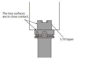 HSK is a shank standard for high-speed rotation developed in Germany. HSK stands for “Hohlschäfte-Kegel” in German, and means hollow shank tapers.
HSK shanks have a shorter overall holder length and a hollow internal structure that is lightweight in order to support high-speed spindle rotation. The size of the taper is fixed, and a 1/10 taper is adopted, where the diameter is 1 mm shorter for 10 mm in the axial direction. It offers high rigidity due to the dual contact system in which the end faces of the taper part and shank are in close contact with the main spindle. Shank sizes are also specified, with six main types used: 25, 32, 40, 50, 63, and 100. Smaller numbers indicate smaller shank sizes.
“Polygonal taper interface with flange contact surface”, also well-known as Coromant Capto, is a standard for tool holders for lathes and TCs developed by Sandvik, a leading Swedish cutting tool manufacturer. It became an International Organization for Standardization (ISO) standard in 2008 and is widely used as a standard system for tool changing on lathes and TCs.
It is a polygonal shape with 1/20 taper and dihedral constraint, as with HSK and BBT. There are six sizes: C3, C4, C5, C6, C8, and C10. Smaller numbers indicate smaller sizes.
Tool holders for MCs can majorly be categorized into 1) collet chucks, 2) shrink chucks, and 3) hydraulic chucks.

Collet chucks are widely used in machining sites for their easy attachment of cutting tools with high tool gripping force. The tapered collet opens and closes to attach, detach, and fix the tools.
Collet chucks come in a variety of shapes and can grip cylindrical workpieces as well as tools. For this reason, there are cases where collet chucks are used on lathes.
There are two main types of collet chucks used as tool holders on MCs: “Push-out type” and “Draw-in type”.
With the push-out method, by turning the nut on the tip of the collet chuck and pushing the collet inside, the collet is closed, and the tool is firmly gripped.
With the draw-in method, by using the screw on the bottom of the collet to pull the collet inside, the collet is closed, and the tool is gripped tightly.
Shrink chucks are chucks that utilize the nature of metal, which expands when heated and shrinks when cooled, for gripping tools.
The process of how the shrink chuck works is as follows. At first, the tool holder is heated by a heating device. Then, the tool is inserted into the inner diameter of the shank, which has been expanded by heating. The tooling is then cooled with water or other coolant. The result is that the inner diameter of the shank shrinks and the tool is fixed. To do this process, a special heating device is required.
This method has higher rigidity and run-out accuracy than other tool holders, and is effective for machining of hard materials and high-precision machining using small-diameter tools. Because a dedicated heating device is utilized, it is not dependent on the skill level of the operator, and the high repeatability of attachment is also a key advantage of this method.
Hydraulic chucks use a cylinder that adjusts oil pressure with a screw to pressurize and grip tools. It is easy for anyone to grip a tool with a single hexagonal wrench. Hydraulic chucks have extremely high run-out accuracy and are often suited for finishing operations. In addition, oil has a high ability to absorb vibration energy and reduce the vibration generated during machining. However, compared to other types of chucks, such as collet chuck, there are some issues in terms of rigidity. Tool holder manufacturers are therefore working on the development of hydraulic chucks with improved rigidity.
 In addition to the three tool holders introduced above, there are many other types of tool holders for MC, such as arbors for attaching indexable milling tools, drill chucks for holding drills, tool holders used for tapping, boring bars for boring, etc.
One of the tool holders that increase the functionality of the MC’s main spindle is angle head. The angle head is a tool holder that changes the machining direction of the tool to a specific angle, which allows machining with one new axis added to the existing MC. As a result, by effectively utilizing the angle head, various machining operations can be performed with only one attachment of the workpiece to the table, improving machining efficiency.
The speed-increasing spindle is also a tool holder that boosts spindle performance. It is attached to the main spindle of an existing MC to increase the spindle speed. Even in fine machining, where high spindle speed is required, existing MCs can be operated with the speed-increasing spindles.
March 24, 2022
March 31, 2022
Share On :


